Every drone needs a brain.
Without it, you’re holding an expensive paperweight with spinning blades.
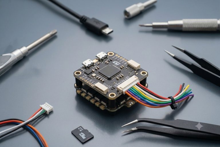
That brain is called a flight controller—but most people have no idea what it actually does.
What is an Inertial Measurement Unit (IMU)?
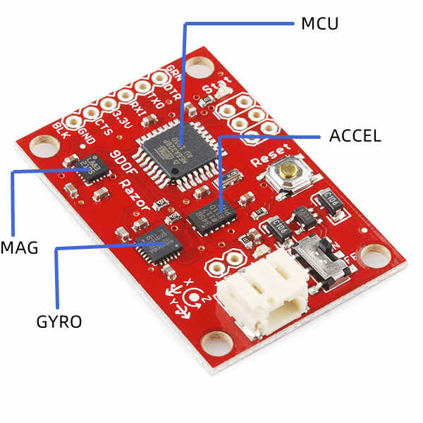
An Inertial Measurement Unit (IMU), also known as an Inertial Reference Unit (IRU) or Motion Reference Unit (MRU), packs a 3-axis accelerometer and a 3-axis gyroscope, making it a 6-axis IMU. Some also include a 3-axis magnetometer, turning them into 9-axis IMUs.

Together, these sensors measure specific force, angular rate, and magnetic fields around the device, providing a comprehensive picture of its motion.
IMUs are crucial in guiding a range of vehicles, from motorcycles and airplanes to missiles.
They play a vital role in attitude and heading reference systems, contributing to the precise control and maneuvering of these vehicles.
Additionally, IMUs are integral in spacecraft, aiding navigation in outer space for Unmanned Aerial Vehicles (UAVs), satellites, and landers.
IMUs also enhance GPS reliability in challenging environments, ensuring accurate navigation in places like tunnels or areas with electronic interference.
What Are the Components of IMU and How Do They Work?
An Inertial Measurement Unit operates by detecting linear acceleration through accelerometers, measuring rotational rate with gyroscopes, and, in some cases, employing a magnetometer for heading reference.
Each principal axis—pitch, roll, and yaw—typically includes one accelerometer, gyroscope, and magnetometer, providing comprehensive data on the object's motion and orientation in three-dimensional space.
Accelerometers
Accelerometers, the nifty devices that gauge and relay specific forces, come in a variety of flavors, including mechanical, quartz, and MEMS accelerometers.
Mechanical accelerometers can achieve in-run bias stabilities less than 1 µg but are mainly used in navigation-grade applications due to their size and cost.
Quartz and MEMS accelerometers offer in-run bias stability ranging from 1000 µg to 1 µg, covering various performance categories. With high precision and stability, they are often employed in industries where accurate measurement of acceleration is essential, such as aerospace, defense, automotive testing, and geophysical exploration.
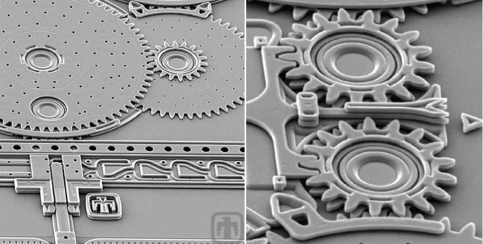
In IMUs, the accelerometers often use MEMS technology, which stands for microelectromechanical systems.
These accelerometers have a tiny mass connected to a reference system by a spring.
This setup allows them to measure how fast something is speeding up or slowing down.
They keep track of the mass's movement using capacitors, and special electronic components.
When the accelerometer is not moving, the mass creates a specific capacitance, like a baseline, showing no acceleration.
But when there's acceleration, the mass moves, and this changes the capacitance.
The accelerometer then measures this change electronically, adjusts it for accuracy, and processes the data to figure out how much acceleration is happening.
Source from siliconsensing.com
This whole process follows Hooke's law and Newton's second law, where the mass moves in proportion to the applied acceleration.
In simple terms, it's like a tiny sensor that senses how fast something is speeding up or slowing down.
Gyroscopes
Gyroscopes in an IMU measure angular velocity, indicating how fast and in what direction something is rotating.
There are various types of modern gyroscopes, including mechanical gyroscopes, fiber-optic gyroscopes (FOGs), ring laser gyroscopes (RLGs), and quartz/MEMS gyroscopes.
Quartz and MEMS gyroscopes find applications in consumer, industrial, and tactical markets, while fiber-optic gyroscopes cover all performance categories.
Ring laser gyroscopes have in-run bias stabilities ranging from 1 °/hour to less than 0.001 °/hour, suitable for tactical and navigation grades.
Mechanical gyroscopes, the highest-performing, can achieve in-run bias stabilities of less than 0.0001 °/hour.
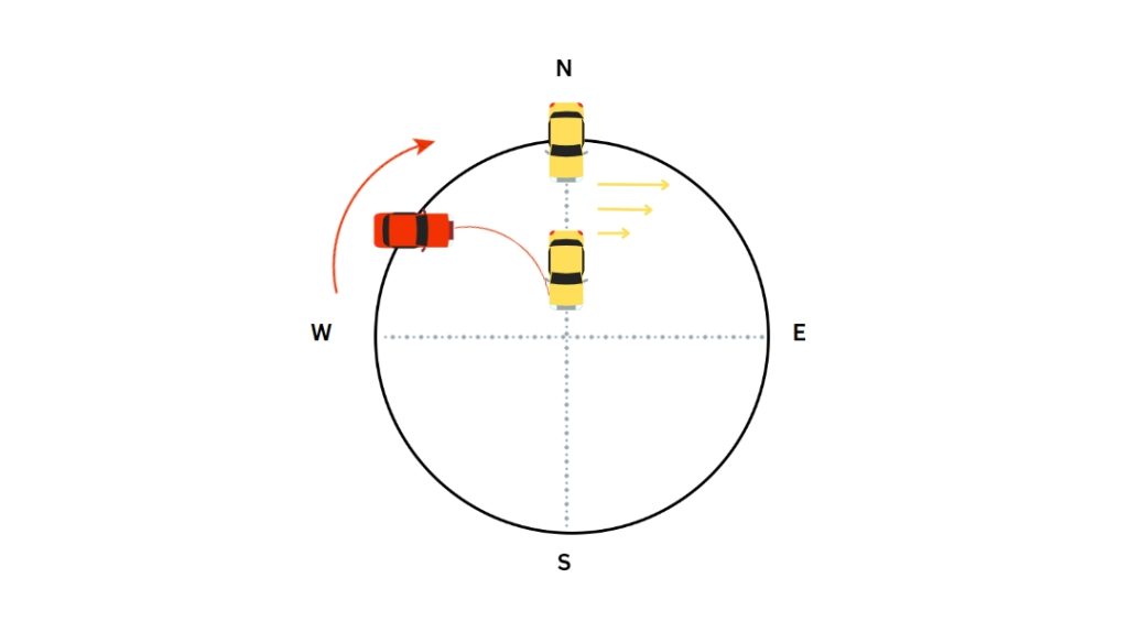
MEMS gyroscopes, commonly used, rely on the Coriolis effect - a phenomenon describing forces when an object moves in a rotating frame of reference.
The Coriolis effect in MEMS gyroscopes is illustrated by a circular platform rotating clockwise.
If a vehicle moves northward from the center, the Coriolis effect causes it to follow a curving arc to the west.
To maintain a northward course, the vehicle applies Coriolis acceleration.
In Earth's frame of reference, the Coriolis effect causes apparent deflection due to the Earth's rotation and latitude.
For instance, launching a rocket northward results in a left-curved path due to Earth's rotation.
In a typical Coriolis MEMS gyroscope, a vibrating proof mass is attached to a reference frame, inducing a secondary vibration perpendicular to the drive axis when rotated.
This secondary vibration sensed through changes in capacitance, provides a signal proportional to the Coriolis force and the sensed rotation.
Magnetometers
A magnetometer is a device that measures the magnetic field, including its strength and orientation.
Common examples include compasses, which determine the direction of the Earth's magnetic field.
Some magnetometers measure magnetic dipole moments, which involve closed loops of electric current or pairs of poles.
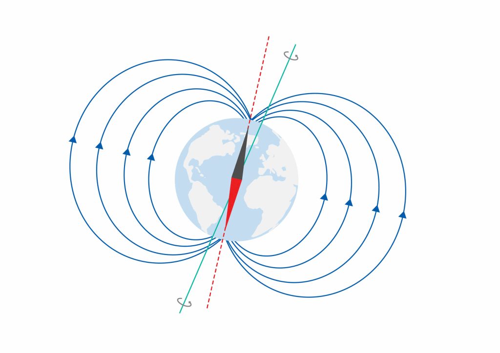
Source from advancednavigation.com
Various magnetometers work by aligning with magnetic fields, canceling forces through the Hall effect, magneto induction, or magnetoresistance.
Hall Effect Magnetometers
The Hall effect involves the generation of a voltage difference (Hall voltage) across a conductor when exposed to an applied magnetic field perpendicular to the current flow.
This principle allows magnetometers to use semiconducting materials, passing current through them and detecting changes in current due to nearby magnetic fields.
The resulting Hall voltage is proportional to the strength of the magnetic field.
Magneto Induction Magnetometers
Magneto Induction assesses how magnetized a material becomes when exposed to an external magnetic field.
This involves creating demagnetization curves, also known as B-H or hysteresis curves.
These curves measure the magnetic flux and force experienced by a material when subjected to varying magnetic fields.
Scientists and engineers use these curves to classify materials based on their magnetic properties and responses to external magnetic fields.
Magneto-Resistance Magnetometers
Magnetometers using this method assess an object's ability to change electrical resistance when exposed to an external magnetic field.
Specifically, they leverage the anisotropic magneto-resistance (AMR) of ferromagnets.
When subjected to a magnetic field, the spins of the electron orbitals in the material redistribute themselves, affecting electrical resistance.
The resistance is highest when the current aligns with the external magnetic field.
IMU Without Magnetometer vs. With Magnetometer
The inclusion or exclusion of a magnetometer in an IMU can have a significant impact on its capabilities and the type of information it can provide.
IMU Without Magnetometer:
When we talk about an IMU devoid of a magnetometer, we're essentially discussing a sensor system that relies solely on accelerometers and gyroscopes to glean information about an object's motion.
In this configuration, the IMU excels at providing fundamental data on linear acceleration and angular velocity.
Its focus lies in deciphering basic changes in orientation, with the accelerometers capturing linear acceleration and the gyroscopes tracking angular rate.
However, the absence of a magnetometer presents certain limitations, particularly in the realm of heading accuracy.
Without the capability to directly sense the Earth's magnetic field, determining precise heading becomes a challenge.
The system may encounter drift over time due to inherent gyroscopic errors, making it less suited for applications requiring highly accurate directional information.
In terms of applications, an IMU without a magnetometer finds its niche in scenarios where rudimentary orientation data suffices.
Moreover, it is often preferred in environments where concerns about magnetic field interference are pronounced.
IMU With Magnetometer
Conversely, an IMU equipped with a magnetometer introduces a new dimension to its capabilities, significantly enhancing the system's ability to provide accurate heading information.
The magnetometer measures the Earth's magnetic field, allowing the IMU to correct for gyroscopic drift and offer improved stability in determining orientation changes.
While this integration of a magnetometer enhances heading accuracy, it also introduces considerations related to calibration.
IMUs with magnetometers typically require calibration on the vehicle or in situ to compensate for static magnetic interference that may introduce heading errors.
Magnetometer calibration becomes a critical step post-installation if precise magnetometer heading is a requirement.
Despite potential challenges, the advantages in accuracy, especially in scenarios demanding precise heading information, make an IMU with a magnetometer well-suited for applications like navigation systems, robotics, and augmented reality.
Types of Inertial Measurement Units
Different types of IMUs, including Silicon MEMS IMUs, Fiber Optic Gyro (FOG) IMUs, Ring Laser Gyro (RLG) IMUs, and Quartz MEMS IMUs, offer unique advantages and are suited for different applications. Here's an overview:
Silicon MEMS (Micro-Electro-Mechanical Systems) IMUs
Silicon MEMS IMUs revolve around miniaturized sensors measuring mass deflection or the force required to hold a mass in place. Although they traditionally exhibit higher noise, vibration sensitivity, and instability parameters compared to FOG IMUs, ongoing technological advancements are steadily enhancing their precision.
Given their compact size, lighter weight, and cost-effectiveness, Silicon MEMS IMUs find widespread use in consumer electronics, featuring prominently in smartphones, tablets, and gaming devices for motion sensing and gesture recognition.
They are also crucial in automotive applications, aiding in vehicle stability control and rollover detection, as well as in navigation systems and advanced driver-assistance systems (ADAS). Within the field of robotics, Silicon MEMS IMUs are essential in ensuring precise movement and positioning.
Source from findlight.net
Quartz MEMS IMUs
Quartz MEMS IMUs feature a one-piece inertial sensing element crafted from quartz, driven by an oscillator to vibrate precisely.
This vibrating quartz senses angular rate, producing a signal that can be converted into a DC signal proportional to the rate.
Known for high reliability and stability over temperature, tactical-grade quartz MEMS IMUs rival FOG and RLG technologies in SWaP-C (size, weight, power, and cost) metrics.
These IMUs have found their footing in industrial automation, particularly in robotic arms and automation systems requiring precise control and positioning.
Quartz MEMS IMUs are utilized in the field of unmanned aerial vehicles (UAVs), providing essential data for stabilization, navigation, and control during flight operations.
In the medical sector, these IMUs are integrated into medical equipment for patient monitoring and motion tracking, as well as in prosthetics and rehabilitation devices.
FOG (Fiber Optic Gyro) IMUs
FOG IMUs employ a solid-state technology where beams of light traverse through a coiled optical fiber. Recognized for being less sensitive to shock and vibration, offering excellent thermal stability, and delivering high performance in critical parameters, they shine in mission-critical UAV applications demanding exceptionally precise navigation.
While larger and pricier than MEMS-based counterparts, FOG IMUs have carved out a niche in aviation and aerospace.
They are integral to aircraft for navigation, attitude control, and stabilization, as well as in space exploration missions for maintaining precise orientation. Additionally, FOG IMUs find application in the defense sector, where they are employed in military aircraft, vehicles, and missiles for navigation and targeting purposes.
RLG (Ring Laser Gyro) IMUs
RLG IMUs operate on a similar principle to FOG IMUs but replace the coiled optical fiber with a sealed ring cavity.
Acknowledged as the most accurate option, RLG IMUs also bear the tag of being the costliest and typically larger compared to alternative technologies.
RLG IMUs find their niche in high-performance navigation systems.
They are extensively used in aircraft and ships, providing precise control over orientation during maneuvers.
In military applications, RLG IMUs are crucial components in tanks, armored vehicles, and precision-guided munitions, contributing to accurate targeting and missile guidance.
Applications of Inertial Sensor
IMUs find diverse applications across various industries due to their ability to measure acceleration, angular rate, and sometimes magnetic field strength. Here are some key applications of IMUs:
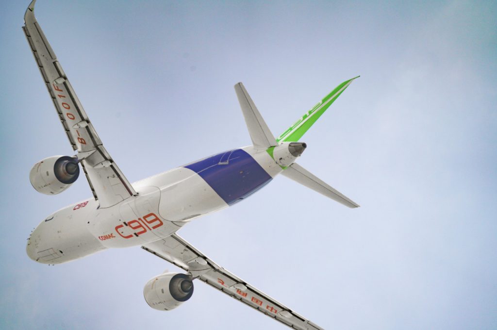
Aerospace and Aviation
IMUs furnish real-time data on aircraft attitude, angular rates, and accelerations, essential for flight control systems, autopilots, and inertial navigation.
Their role extends to gyrostabilization, refining sensor accuracy, and optimizing targeting systems.
In military aircraft, IMUs contribute to radar and targeting systems, while in spacecraft, they guide orientation during critical phases like orbit insertion.
IMUs also enhance Vision Systems, ensuring aircraft stability in low-visibility conditions.
Moreover, they facilitate in-flight monitoring for real-time diagnostics and anomaly detection, promoting safety and operational efficiency.
Robotics
In robotics, IMUs serve a pivotal role in enhancing dynamic motion control.
IMUs provide real-time data on acceleration and angular rates, enabling robots to navigate, interact with their environment, and execute tasks with increased precision.
These units contribute to the overall intelligence and responsiveness of robotic systems by offering essential information about their spatial orientation and movement.
Integrating IMUs into robotic platforms facilitates improved path planning, obstacle avoidance, and manipulation of objects, ultimately enhancing the efficiency and adaptability of robotic operations.

Virtual Reality and Augmented Reality
In Virtual Reality (VR) and Augmented Reality (AR), IMUs are instrumental in tracking and enhancing user experiences.
IMUs are integrated into headsets to precisely capture and interpret the user's head movements in real-time.
This tracking information is then utilized to dynamically adjust the displayed content, creating a seamless and immersive interaction.
Whether exploring virtual environments or interacting with augmented content overlaid in the real world, IMUs enable responsive and accurate head tracking, contributing significantly to the overall sense of presence and immersion in VR and AR experiences.

Automotive
IMUs are integral components in automotive applications that contribute to electronic stability control systems, rollover detection, and advanced driver assistance systems (ADAS).
IMUs enable precise monitoring of the vehicle's dynamics, ensuring stability during maneuvers and enhancing overall safety.
These units provide real-time data on acceleration, angular rate, and orientation, aiding in the execution of dynamic control algorithms that optimize vehicle performance and responsiveness.
Additionally, IMUs play a crucial role in enhancing the accuracy of navigation systems, particularly in situations where GPS signals may be unreliable or unavailable.
Sports and Fitness Tracking
In sports and fitness tracking, IMUs are often embedded in wearable devices.
These devices leverage IMU data to capture and analyze a user's movement patterns and biomechanics during physical activities.
IMUs precisely measure accelerations and angular velocities, providing valuable insights into an individual's performance, form, and overall athletic movements.
This data, when processed and interpreted, aids in the assessment of gait, stride, posture, and specific exercises.
The information derived from IMUs is utilized to enhance training programs, monitor progress, and offer real-time feedback to athletes and fitness enthusiasts, contributing to improved performance and injury prevention.
Moreover, IMUs are indispensable in the development of smart sports equipment, such as connected footwear and apparel, enabling a deeper understanding of athletic kinetics and facilitating personalized training regimens.

Industrial Applications
In industrial applications, IMUs are employed for machinery monitoring and predictive maintenance.
They assist in detecting vibrations, shocks, and changes in orientation, thereby enabling proactive strategies to ensure equipment reliability and minimize downtime.
Additionally, IMUs contribute to the optimization of industrial processes by providing real-time data on the dynamic behavior of machinery, aiding in performance analysis and operational efficiency improvements.
Healthcare and Biomechanics
In healthcare and biomechanics, IMUs are used for tracking and analyzing human movement.
They are integrated into wearable devices and research tools to provide detailed insights into motion patterns, joint angles, and accelerations.
These devices are instrumental in monitoring patient movements for rehabilitation purposes and conducting biomechanical research to enhance our understanding of human motion dynamics.
IMUs contribute valuable data that aids in developing personalized rehabilitation plans, assessing gait abnormalities, and advancing biomechanical research to improve clinical outcomes and enhance our comprehension of human movement kinetics.
Geophysical Exploration
In geophysical exploration, IMUs are utilized to enhance the accuracy of seismic surveying by precisely measuring ground movements and vibrations.
They contribute to the identification of subsurface structures and the delineation of potential natural resources through their ability to capture detailed information about seismic waves and ground responses.
This data aids geophysicists in creating accurate subsurface models for resource exploration and geological analysis.
Military and Defense
IMUs are vital for navigation, targeting, and ensuring stability and precision in diverse systems.
IMUs play a crucial role in missile guidance, inertial navigation for submarines, and enhancing the accuracy of military vehicles, particularly in challenging terrains.
They contribute to the overall effectiveness and reliability of defense systems by providing real-time and accurate information about acceleration, angular rate, and orientation.
Additionally, IMUs are employed in stabilization systems for weaponry, ensuring precise targeting and delivery of munitions.
Their use extends to unmanned aerial vehicles (UAVs), where IMUs facilitate stabilized flight and accurate navigation for surveillance and reconnaissance missions.
In the context of military and defense, the robust and dependable performance of IMUs is paramount for mission success and strategic operational capabilities.
Consumer Electronics
In consumer electronics, IMUs enhance user experience and enable innovative functionalities.
They are integrated into devices such as smartphones, tablets, and gaming controllers, providing essential motion-sensing capabilities.
IMUs contribute to features like screen orientation, gesture recognition, and interactive gaming controls, creating a more immersive and responsive interaction with electronic devices.
The precise measurement of accelerations and angular rates by IMUs enables dynamic adjustments and intuitive control mechanisms, significantly influencing the usability and functionality of consumer electronics.

What is the IMU in a Drone?
Now, let's talk about how IMUs work with drones.
They're a key player in keeping these unmanned aerial vehicles steady and in control, especially when dealing with challenges like strong winds or sharp turns.
IMUs are always at work, measuring acceleration and rotation, and feeding instant data to the flight control system.
This quick feedback ensures that the drone flies smoothly and stays under control.
IMUs also make some cool things happen like precise station-keeping and autonomous waypoint following.
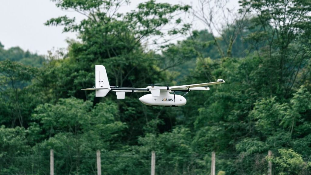
The JOUAV CW-15, a VTOL drone created with IMU capabilities
Basically, this means drones can hold a position or follow a set route all by themselves.
This feature is a big deal for surveillance, mapping, and deliveries.
And there's more—IMUs provide data for fancy systems like Attitude and Heading Reference Systems (AHRS) and Inertial Navigation Systems (INS).
AHRS gives real-time info about which way the drone is pointing, and INS takes it up a notch by figuring out both the direction and exact position.
This detailed data is super important for making sure the drone navigates accurately and stays under control.
The number of inertial measurement units (IMUs) on a drone can vary based on its design and purpose.
Many consumer drones, especially smaller ones, often have a single IMU to keep costs down. This IMU typically contains sensors such as accelerometers and gyroscopes to measure linear acceleration and angular rate, respectively.
Larger and more advanced drones, especially those used for professional or industrial purposes, like JOUAV CW-15, may have multiple IMUs for redundancy and improved accuracy.
Redundancy is important in case one IMU fails, as it helps ensure the drone can still operate safely.
Read More
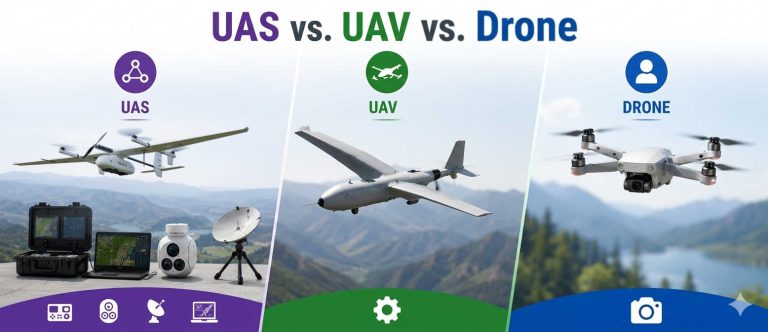
Let’s be honest: the drone world loves its acronyms. UAV, UAS, drone, RPAS, UCAV, FPV–it’s an alphabet soup. And most people use them like they’re the same thing.
They’re not.
And here’s why that matt
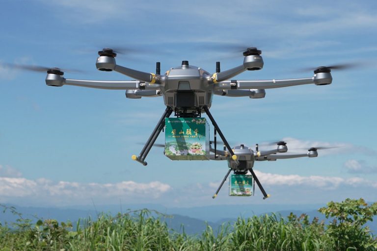
An airborne cargo drone is exactly what it sounds like: an unmanned aircraft built to carry stuff. Not tiny packages for a suburban backyard – real cargo. From medical supplies to industrial parts.
An

JOUAV Product News and Use Cases
Fixed-Wing VTOL Drones Insights and Industry Trends
Invitations to online demo events